
 EN
EN TR
TR
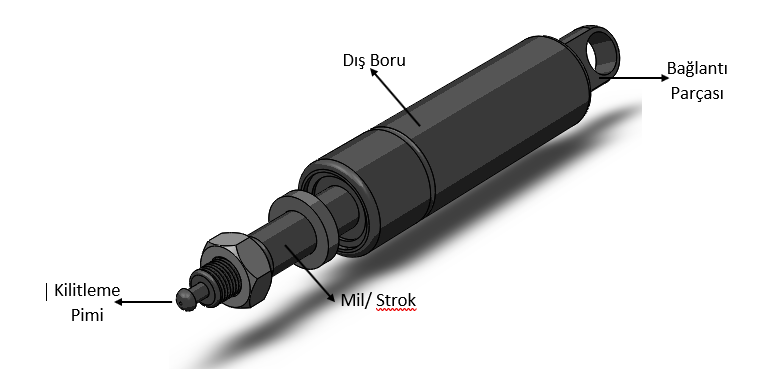
LOCKABLE GAS SPING - KY500001
FORCE: 700 N
STROKE: 25.5 mm / FULL LENGTH: 183 mm
ROD DIAMETER: 12 mm / TUBE DIAMETER: 27 mm
THREAD LENGTH: 20 mm
Ürün Özellikleri

LOCKABLE GAS SPRİNG
Weights to our tools, adjusting, moving, hydropneumatic mechanisms that help us easily or with no effort.
Lockable Gas Springs; It has a valve direction that allows the shock absorber strobe to be held in any position when the locking pin is pressed. This valve preference is triggered by a pin-connected shaft/stroke. When the locking pin is pressed, the pin is released. If the locking pin is released, it will be locked.
Internal Design of Lockable Gas Springs, piston rod, piston valve, cylinders, guides, gaskets etc. consists of business. Internal pressure is created by gas (nitrogen) and oil.
Lockable Gas Springs are used in a large number such as Hospital Beds, Hospital Furniture, Dentist Chairs, Operating Tables, Working Tables, Emergency Carts, Passenger Seats, Wheelchairs.
OPEN POSITION

With the locking pin pressed; The valve group inside the locked shock absorber outer tube exerts pressure on the pressure oil chamber rear cavity in the +x-axis direction. Meanwhile, the oil transfer hole on the shaft/stroke is in the open position since the valve group in the outer pipe is pressurized in the +x-axis direction. The pressurized oil chamber passes through the locking pin surface from its rear cavity to the valve assembly through its cavities. The transfer process is realized by passing through the oil transfer hole on the shaft/stroke body, which provides oil flow to the shock absorber by transfer from here through the passage channels, to the front oil chamber of the shock absorber. In this position, the damper is open.
LOCKED POSITION

During the operation of the shock absorber in the opposite direction, oil is transferred in the opposite direction and the process is performed with the same performance.
While the working principle of the shock absorber is realized, when the force applied to the locking pin is removed while the stroke distance is in any position, the valve hole located on the shaft that provides the oil flow of the shock absorber, instantly pushes the valve group forward with the reaction of the mechanisms in the interior design. At this stage, the transfer process is stopped by closing the oil transfer hole on the shaft. The shock absorber is fixed in the desired position.


